
80 METRE RECEIVER

This 80M receiver design includes the necessary switching to allow the SSB filter and first I.F. amplifier to be used for transmitting. The receiver stages from R.F. input to speaker output will be described in detail below.
BAND PASS FILTER
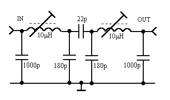
This type of band pass filter gives very good attenuation at frequencies that are higher than the passband. This is desirable because diode dbm's are very prone to harmonic mixing. This filter should keep out strong VHF signals. The good H.F. rejection of this filter will also reduce the possibility of I.F. breakthrough.

FREQUENCY RESPONSE PLOT
When properly aligned and terminated by 50 Ohms at both ends, the 1dB bandwidth is 300KHz, from 3.500 to 3.800 MHz
The 10 microHenry inductors were hand wound on TOKO 10K coil formers. I used 25 turns of thin copper wire. To calculate the inductance of a home brew coil on a toko 10K former, use the following formula.
 Where L is
inductance in microHenries, N is the number of turns. In this example:
16*(25*25) = 10000 / 1000 = 10 microHenries.
At best, this is just a rule of thumb but in practice it gives surprisingly accurate results.
MIXER

For best results, use a high-level DBM. Mixers that have very good strong signal performance require +17 to +23dBm of local oscillator drive. Unfortunately, such mixers are very expensive. It is not difficult to build a home made mixer with similar performance. The mixer above uses a ring of four 1N914 high speed switching diodes.
Philips 1N914 Diode.
Maximum dissipation 250 mW at 25C
Maximum reverse voltage (PIV) 75V
Maximum continuous forward current 75 mA
Maximum repetitive forward current 225 mA
Forward voltage drop VF 1V at 10 mA
Diode Capacitance C max 4pF, Typical 1pF at 0V
The switching diodes can be replaced with proper Schottky mixer diodes like the BA481. With 3.7MHz on the R.F. port, 11.5MHz on the L.O. port and a 7.8MHz I.F, the 1N914's seem to be just as good.
The transformers were wound on ferrite toroids. I used eleven turns, trifilar wound on ferrite toroids. See the receiver section of the SSB transceiver project rx.html for details. Local oscillator injection is +23dBm. After the 3dB attenuator pad, the local oscillator power is +20 dBm (100mW.)
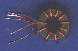
MIXER TRANSFORMERS
DIPLEXER
To get the best performance from a dbm, all ports should be properly terminated. It is particularly important that the I.F. port is properly terminated. The diplexer between the mixer I.F. port and the post mixer amplifier, ensures that the mixer has a 50 Ohm termination at all frequencies.

The reactance of L and C should be 50 Ohms at the I.F. frequency. The values at the top of the page are for a 7.8MHz I.F. The 5.02 microHenry inductors are: 18 turns on a Toko 10K former. Two capacitors are connected in parallel to get the required C of 408pF.
Try: The QRP Homebuilder Webpage for a useful diplexer design program for Windows.
POST MIXER I.F. AMP.
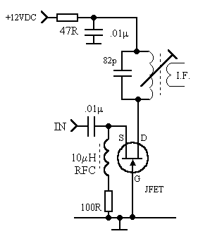
The post mixer amplifier is a standard grounded gate J-FET amplifier. I used a J113 FET. I haven't tried one, but the 2SK125 should be a suitable replacement. The output transformer is chosen to match the I.F. frequency. I used an 18 turn primary and 4 turn secondary, on a Toko 10K former.
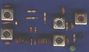
FRONT END PCB
I.F. AMPLIFIER AND PRODUCT DETECTOR
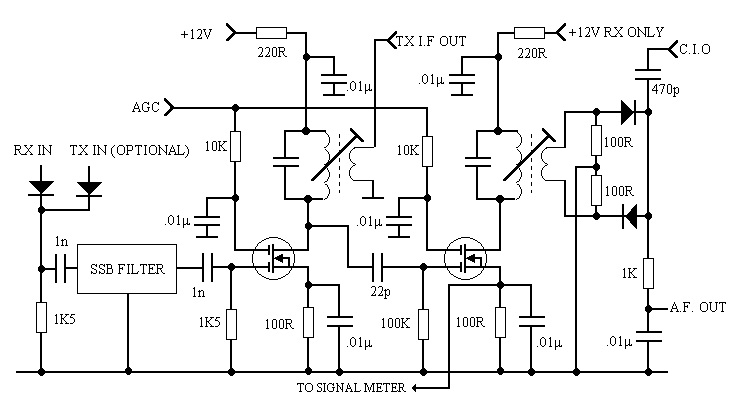
I used 1N914's as the filter RX/TX switching diodes. I had no proper PIN diodes in my junk box. The mosfets are 3SK45's, most VHF dual gate mosfets should work just as well. The I.F. transformers are identical to the one in the post mixer amplifier (above.) I used a pair of 1N34 Germanium point contact diodes for the product detector. The 7.8MHz SSB filter was removed from an old CB radio.

Alternative arrangement for the I.F. amplifier. The FET/BJT cascode amp is popular with Russian homebrewers.
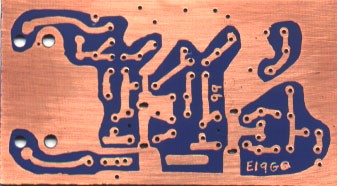
HAND DRAWN PCB
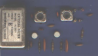
I.F. AMP/PRODUCT DETECTOR
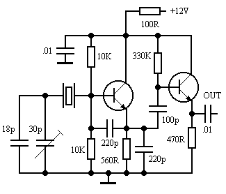
CARRIER INSERTION OSCILLATOR
The C.I.O. is a standard, common collector, Colpitts oscillator. I used a pair of 2SC1675 transistors. A couple of 2N2222's should work just as well. The crystal (7.7985MHz) is in a socket. I can change to USB by changing the crystal. The circuit was built on the copper side of some PCB. It gives a whole new meaning to the term "Ugly Construction."

UGLY CONSTRUCTION

A.F. AMPLIFIER
The audio amplifier is quite easy to build. I used a BC109 transistor for the pre-amp. Audio for the AGC circuit, is taken from Point 'X'

AGC CIRCUIT
The AGC circuit generates a negative voltage, which is applied to gate 2 of the mosfet I.F. amplifiers. The transistor is a BC109. All diodes are 1N4148's.

SIGNAL METER
The voltage at the source of the second I.F. amp. is used to drive the s-meter. Use the 1K pot to zero the meter . Use the100K pot to set the maximum meter deflection, when receiving a very strong signal.

V.F.O. AND BUFFER AMPLIFIER
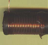
L is 16 turns on a 0.5in ceramic former (section of old 1KW electric heater element.) Try using 20 turns, then adjust the tapping point until the oscillator is running at 11.5MHz. The fet's are J113's. The transistor is a 2N2222A.
L
Hear the end result. k1ir.wav Wav audio file.