MICROPHONE AMPLIFIER, LPF AND BALANCED
MODULATOR
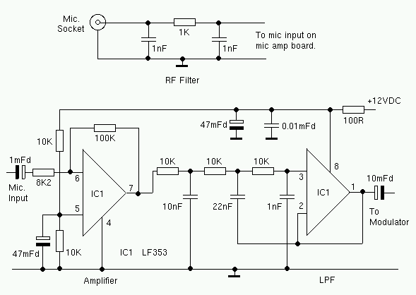
 MIC AMPLIFIER AND LPF
The microphone amplifier has a
gain of more than 20dB. The amplifier is followed by an 2.7KHz active low pass
filter. A dual op-amp is used for both stages. The choice of op-amp is not
critical. I use an LF353 but most dual op-amps should work in this circuit.
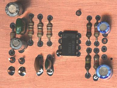
 MIC AMP PCB TOP VIEW
Like all the other circuit boards
in this transceiver, the PCB was drawn by hand. I used double-sided PCB. All
ground connections are made to the top PCB foil (Ground plane). The holes for
any component leads that are not grounded, must be reamed out (countersunk?)
with a suitable tool. I used a 3mm HSS drill bit.
 OSCILLATOR/MODULATOR
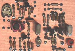
 OSC/MOD PCB Top view
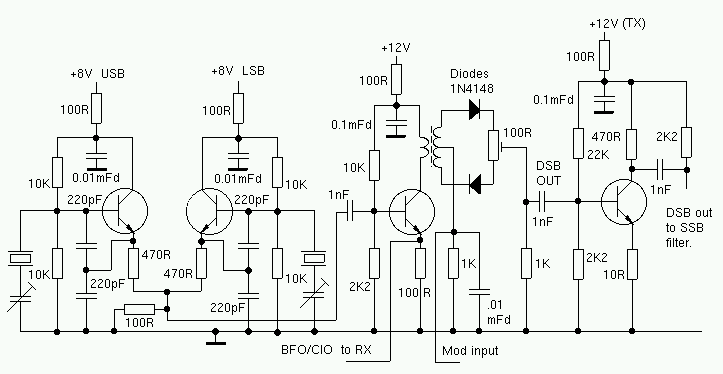
The carrier oscillator/balanced
modulator unit is very similar to the circuit used in the 80M SSB rig. All transistors
are 2SC710's. Any general purpose NPN transistor with an ft of a couple of
hundred MHz should be suitable. I used BC547's in the 80M rig. The transformer
is 6 turns, trifilar wound on a medium to high permeability ferrite core.
 Details of transformer phasing.
I tried several types of
diode in the balanced modulator. OA91 and 1N34 point contact diodes worked well.
1N4148 silicon diodes also gave rood results. I decided to use the 1N4148's, as
they are more readily available.
Wav file of my first test of the
transmitter: test.wav
17KB
BACK TO HF TRANSCEIVER
PAGE
EI9GQ HOME BREW RADIO
PAGE


